
Welcome!
Be part of our community & join our international next generation forum now!
Categories
In this Discussion
- bentstick October 2013
- captainshooch October 2013
- CatfishJim December 2013
- cooperville October 2013
- crozdog May 2013
- crystal_skull November 2013
- FullySilenced July 2013
- Lloyd December 2013
- moscca July 2013
- Myles December 2013
- Philter July 2013
- punkin November 2013
- Smaug October 2013
Homebuild with StillDragon Fittings
Before I joined here I asked Lloyd if it would be OK to show "not quite a StillDragon" equipment. Well I just heard my shipment of SD bits is on its way from Smaug, so I thought I would let you know what is in the pipeline.
I made a potstill - this one with a built in pre condenser, and a 25" two core concentric shotgun product condenser.
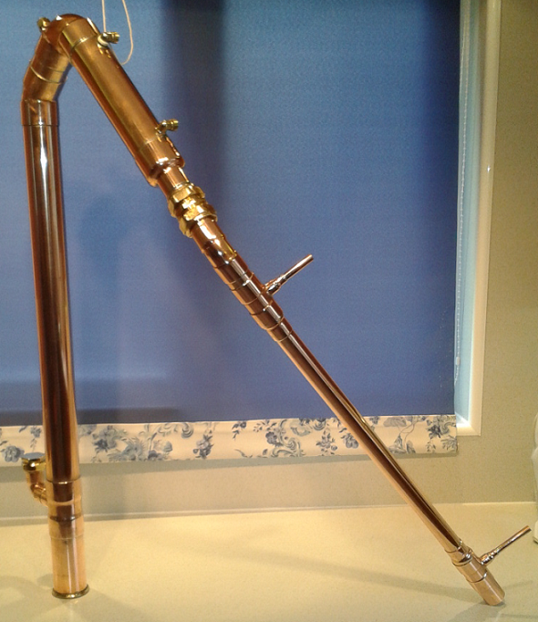
Well it has already gone, as part of an integrated rig. It is going to be updated with a 2" brass SD ferrule for the keg connection, instead of the homebuilt version.
It is going to be combined with a thumper mounted, 3" SPP packed, VM / LM combined column like this. 5 litres of SPP is on its way from Odin.
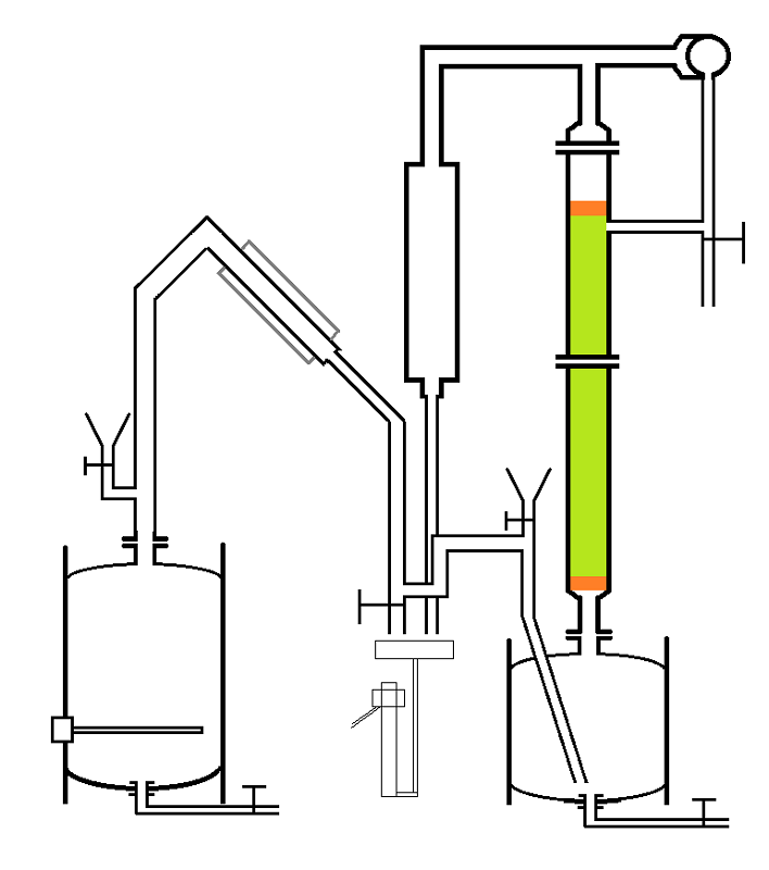
Brass SD fittings on the column, which because it is in a still room will be un-insulated and polished. I am giving it a 3 core shotgun condenser. Both kegs are getting drains, valved refill ports and levelling feet. Coolant hoses are going to be 10 mm bore platinum cured silicone.
The intention is that the new owner will just turn a valve or two to switch off the coolant to the pot still, and route the vapour path into the thumper for the column instead. Both condenser outputs will end up in the same parrot. Once set up and running there should be no need to disconnect any tri clamps. Cleaning can be done in situ.
Comments
Wow can't wait to see a photo of the finished unit... nice concept and a lot of insulating work looks like no heating element in the thumper? as a booster?
Yes the keg and thumper will be insulated, but not the column. If it turns out to be needed later on it can be retro fitted, but I hope that due to the enclosed location that it will not be required. I know folks do manage to run uninsulated packed columns in some situations.
The idea is to transfer all (or most of) the volatiles to the thumper, before taking any product from the column. Resulting in a column boiler charge of higher ABV than would be usual. Direct heating of such a charge is not recommended. However, the secondary boiler charge for the column is being heated with steam injection.
50 litre primary boiler, 30 litre secondary.
Beatiful design and construction as always Myles. Your speculator certainly has grown from the simple pot still you were offering... :)) :)>-
StillDragon Australia & New Zealand - Your StillDragon® Distributor for Australia & New Zealand
Will the heat be from the pot still aka primary boiler... the distillate being dropped into the thumper? or will there be live steam injection from an alternative source?
I was somewhat concerned about enough heat to drive the pot, thumper and the column at the same time...
I have never tried or seen an actual set up like this but i like the way it looks on paper...
This is just a variation on the side mounted Holstein column. When the vodka still is in use there is no cooling on the pot still. It just acts as the vapour path between the boiler and the thumper. The full 3 kW that is available for the pot still could be used to heat the thumper. There is no output taken from the pot still as it is all diverted into the thumper.
My thinking is this: Do a strip run on the pot still. Drain and charge the the boiler with the diluted low wines. Lets say 40 litres at 20%. Transfer the distillate, lets say 13 litres at 60%, into the thumper whilst the column is in full reflux and stabilising. That should just about deplete the boiler of volatiles. Then take off heads and product from the column, using the now (mostly steam) that is being generated by the boiler, to heat the thumper.
There should be sufficient volume in the thumper to cope with any increase in volume - bearing in mind that the thumper charge is decreasing as product is also being removed. Just as a precaution I could fit a level indicator tube to the thumper, but I don't think it would be required.
Because the choice was made to use SPP, it might even be possible to do the whole process in a single run from wash in the boiler.
In pot still mode, the coolant is on for the pot still and the valve is open above the parrot. Nothing gets to the thumper or column.
Why use a thumper? You can connect the o/p of the pot to the base of the column via a 3 way ball valve & install a p trap return to the boiler for any liquid which falls out of the column. That would be more energy efficient.
Very nice Myles. You take a lot of pride in your workmanship and polishing.
I also can't wait to see your multi-purpose rig build thread.
The only pressure reflief is on top of the VM/LM reflux condenser? So your also precharging the thumper with Mash or Low Wines of some sort or is the Pot just filling it up from empty each time.. via the reflux condenser?
I bet it works... but I would add a second heating element... not sure 3kw is enought to make it all fly with any speed.
In normal pot still mode the condenser is open to atmosphere. In reflux mode you are correct - pressure relief is via the reflux condenser. I don't normally fit a pressure relief valve to the boiler under a reflux column but it would be easy enough to do. What is your opinion on this - do you use a PSV on your boilers? I have done it on a previous valved configuration but that was for other reasons.
Well as an update:
It has been decided to increase the pot still boiler to a 100 litre 6 kW keg, so it should have plenty of power available to drive the thumper and the column. Even without column insulation. I am glad we are using SPP - I have enough coming for 1m in the 3" column, so it provides the option of mounting the column on the boiler for a MUCH longer duration runtime. Personally I wouldn't - but that is up to the owner. (Oh the recommended max power for this size column with SPP, is 4.8 kW)
You were correct earlier FS, minimal pre-charge with water, the reflux condenser should fill the thumper. I have thought about the pressure relief issue, and may well fit a PSV to the boiler itself. It may never be needed - but it will not hurt to have it there. Venting into a bucket of water perhaps?
These 100 litre kegs are as rare as hens teeth in my part of the world, so I am glad I managed to find one.
As a post script I am going to build a controller for this still using a PSR-40. This is the big brother to the PSR-25 and is good for 9kW. The PSR-25 would cope with 6 kW, but I just don't like to max out any power supply. Increasing to the 40A version means there is plenty of surplus capacity available.
Pot still and attached vodka still in 1 neat and tidy package. Should be nice.
I am building an offset, horizontal coil, reflux condenser with an LM option for heads removal. This uses a 1.4" equal T as the vapour splitter, with a 1.4" entry into a 2" Reflux Condenser, and a 1.4" VM branch into a full bore gate valve.
The valve looks huge on the desk, but it will help to balance the reflux condenser.
No fittings to show yet - but they are coming, I promise.
Have another part of the build to discuss though. I have started preparing the 30 litre keg that will be the thumper under the 3" SPP column. I have decided that this is going to be mounted at the same height as the keg boiler, so I can use an overflow. That way the client could do a full keg vodka run - if he really wants the long run time. ;)
Anyway I cut out part of the upper skirt and gave the dome a slight polish.
I am going to fit short height adjustable legs for drain clearance, bolted to the lower skirt. But I was thinking - I don't really want to clutter up that dome now that it looks "clean", so how about re-locating all the other keg connections to inside the lower skirt. Out of view.
One option is to use a separate overflow connection (not illustrated below) but to use a single fitting for both a vapour injector and the drain. I am thinking a 1" drain with a 1/2" vapour injector - like this:
Vapour in from the left, drain out to the right.
Or use the drain as the vapour injector. After all you never use them both at the same time. :))
Vapour in outside left, overflow inside left, drain right.
Obviously the vapour path needs to have a high point higher than the thumper, but most boiler / thumper configurations would have this anyway.
With the last option I imagine I would cap the drain into the keg and drill holes - sort of like a basin outlet, to act as a vapour diffuser when the vapour was flowing.
What do you think? Any reasons why it wouldn't work / opinions / preferences?
This might help explain a bit better.
Conventional method
Or alternative to keep a clean top dome.
Any opinions?
Do you even need the U bend in the overflow line if the thumper is mounted a bit higher than the max boiler level so that the overflow is higher than the boiler level?
I think you are correct, Myles. The U bend is not needed if the pipe in the small tank is above the maximum working level of the big tank.
Yes Lloyd, the way you have drawn it is the usual way. The only problem for me is fitting a connector at the correct position on the small tank, due to the profiles of the wall. It would be right on the rolling ring, that's why I was thinking of using an overflow pipe mounted vertically through the base.
As for the other end I could easily fit another connector into the big keg, but the drain line is going to be there anyway. It is just a case of swings and roundabouts - could use either, haven't decided yet. My inspiration is this.
Just on a much more modest scale, and having the column selectable, so product can be taken from either the pot still or the column.
I could never run a still like that, Myles. Its just so beautiful I'd be afraid I'd spill something on it and get it dirty.
Is it just me or does that boiler look really small for that column? By the time it got up to temperature the run would be almost over.
Myles, I like the combination of the two of them... the return line from Lloyds drawing and the top entry beside the column on your thumper
... with a clean simple drain... no complex plumbing or pipe in a pipe happenings
Of course that means a fixed height for the thumper... you might have to table mount it all or a small platform at the least maybe a platform that holds the boiler and the thumper so they stay at the correct level
Yes Lloyd I did wonder about the proportions between column and boiler. Don't know if this is just a demonstration or a working still.
So top or bottom entry is a mostly cosmetic issue, both could work. The heights will have to be fixed, both are getting adjustable legs but this is mostly for levelling. The client will have to build a suitable worktop, as once connected they should both have clean-in-place features, and should not need disassembling very often.
The big keg will be floor mounted on a low plinth, just to provide drain clearance of 6" or 8" from the floor. I would be tempted to sit the thumper on a worktop adjacent to the big keg, with the drain valve under the worktop. That would be easier to do with a top mounted vapour inlet.
Unfortunately still no SD fittings to show but this is the 30 litre thumper for the column, more to come.
Top mounted vapour inlet and refil valve.
Central drain and overflow ports
And the adjustable legs
(Inspired by the brilliant SD boilers)
Looks nice Myles,keeping an eye this one!
It is what you make it!
I forgot to add this view of the top dome
It still looks quite clean even with that big compression fitting, the vapour inlet is the side branch and the gate valve will have a funnel attached.
I put the legs (12 mm versions) on the big keg and fitted the drain and element fittings. No drain tube or valve attached yet.
I've been a fan of your work for years Myles and the pictures above are examples why.
those legs don't look strong enough to me, although i overengineer everything i make from metal or wood to make up for my lack of skills (which you obviously don't suffer from Myles.).
StillDragon Australia & New Zealand - Your StillDragon® Distributor for Australia & New Zealand
Maybe a support ring of some type to support the bolts? or a triangle frame of some sort... would not take much it the bolt flex a bit when the keg is filled... keg weight plus 125 pound of liquid plus the column or head weight?
maybe fine the way is is ... i used ss angle for my keg legs...then put wheels on em kinda like LOO drew up three legs though...
Those legs are M12 coach bolts secured in the same way as on the thumper, with 4 nuts to each heavy duty bracket. Each M12 bolt is rated at over 600kg static load. If anything goes it will be the 4 x 5mm bolts that secure each bracket to the keg.
However the shear load on those 4 bolts is more than adequate. I don't anticipate any problems.
I will jump up and down on it to test it and can easily brace the legs to stop them splaying - although I really don't think they will.
They look slender but it is a vertical load onto a steel bolt, wheels might be a different issue, but these are supposed to be static.
Looks great overall ... it may be optical but the legs look spindley... i trust your judgement as you have you hands on the product...
I have been on holiday for the last few weeks but thought I would give you an update. Fitted the drain valve and leak tested.
All is good. No leaks from the drain or element. Full flow with 100 litres in the keg.
Also did a static test on the legs. Filled the keg full to the brim then put another 100 litre keg on top and filled that too. No problem.
These legs are 12mm steel bolts, each held to the bracket with 4 nuts, brackets held to the keg skirt with 4 bolts.
Now don't get me wrong - I would never suggest these were suitable for wheels or for bouncing a full keg round the still room. But for a stationary boiler to get a suitable drain height they are OK. You could brace them easily but the brackets are heavy duty items and you would need to do something daft - like tip a full keg onto 1 side - in order to bend them.
Have made a start on the offset, crossflow, reflux condenser. In reality I brazed the end plates into the 2 sections of 54 mm tube. This condenser has an equal T in the centre. 56% silver solder just to seal the plates inside the tube with a much higher melting point than the soft solder that I will use for everything else.
560 deg C, borax flux, and the minimum amount of solder possible just to seal the plate into the tube without getting excess solder on the area where the tubes will be soldered in place.
Will end up with a tube length of about 300 to 310 mm x 19 x 8 mm tubes.
Top quality work as usual Myles. I'm very interested in your offset X-flow condensor, and how it finishes up.