
Welcome!
Be part of our community & join our international next generation forum now!
Categories
In this Discussion
- CothermanDistilling June 2015
- DocPorter June 2015
- grim June 2015
- jacksonbrown June 2015
- Kapea May 2015
- Littlechicago May 2015
Recirc System Pump needed
So I'm half way through building a new recirc setup.
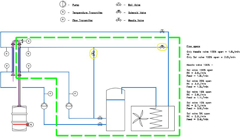
Turns out the control valve that I got on eBay is about the right size for mains pressure but I want to set up a recirc loop like the attached P&ID.
Hopefully I drew it up clear enough to follow.
It's being controlled by an Arduino so I can easily dial in % at the click of a button.
I had the bit within the green boundary set up (minus the cooling coil) and the flow rates I got are listed on the picture.
'RC' is the flow through the condenser (measured by the FT)
'Feed' is the flow returning to the bucket thus the flow feeding into the loop (measured by hand)
The valves referred to in the drawing are the ones clouded in yellow.
The needle valve is just to create a bit of back pressure to force flow out the solenoid valve when it opens. They'll probably both be replaced with an orifice (or a crushed bit of 1/4" copper tube) in the finished set up.
The whole system seemed to work fine but I want more pressure to work with to get the flow rates up.
It looks like the pressure drop of the system is around 5m going off the Chugger pump curve and I'm right on the edge of it.
I was thinking about a Davey SC20-25 (PDF) or a Grundfos UPS 25-60 but now I'm not sure. The curves don't look much different to the Chugger and it was borderline IMO. Probably fine for the PC though.
I think what I want is a cheap, quiet, efficient pump that can do 5L/min @ 1 bar continuous
Any recommendations or better ideas?
Comments
if you have no air in the system, head pressure is nil... the chugger can do the job if your design and piping eliminate air bubbles effectively.. I am cooling an 8" CD RC and PC with a pump only slightly larger than a march809/chugger... I can get 4g/min using 5/8" ID hose of short lengths and designing for low line losses with things like eliminating 90 degree fittings..
A rarely used option is a pool pump. new of course. the pumps are self priming and can handle solids ( basket removed) and no worries on heat or leaching. they are non bpa and rated for hot tub use. flow is fast though, I must warn you. I can empty a 300 gallon ibc in 10-15 min (1" 300 psi hose).
What pipe size is being used?
Cd, static head yes but...
Grim, it's a bit all over the shop.
Hose is 1/2". Condenser fittings are 3/8". The sol orifice is 3.0mm and I'm not sure about the needle but it must be about the same looking at the flows.
Since I'm using excess pressure of the recirc pump to actually feed the loop I need more than 5m head to work with. Maybe I should swap the valves out for 1/2" balls just to see what the flow rates go too.
I understand dynamic head, but I am currently using a pump nly a bit stronger than the 809/chugger (because it is ignition proof, otherwise I would still be using the march 809) and have it pumping to a height of about 15 actual feet right this moment it flows enough for an 8" CD putting out 15liters a minute!!! ... your pump is big enough!
Something as simple as running a flexible hose over a couple hoses and a couple loops creating a half dozen ups and downs with air in them can make a centrifugal pump not work...
I think increasing your line and fitting sizes would be a good place to start. Being a closed loop system your only loses are from friction, which you should be able to reduce to less than 5 meters. This would put you in a better place on the pump curve. If you really need to stay with your line sizes I think you'd need a higher pressure pump than the ones you suggested.
There's a rule of thumb we use in the chemical industry. The best economic trade off between pump/motor cost and piping cost is to keep your pressure drop around 2 psi/100ft. Not sure if it works at this scale...
I think for 1/2" hose, anything under 6L/min will result in flow velocity's of well under 0.5m/s which I believe is completely reasonable going of this. Sure going up in line size would help but I don’t think that’s the issue here.
The point about Static Head and air is a good one so I redid the hosing a bit to make sure it was fully purged.
Having the pump push up hill and not getting the benefit of flowing down hill to cancel out the effort, I guess.
The full flow through the solenoid valve at 100% open (needle valve closed) was still 1.8 L/min just like before so I don't think there was any air in the system causing issues with the other measurements.
The finished system needs to be self purging.
Purging on start-up is fine for a while but during the run the water will release dissolved gases when it heats up. This will build up in a badly designed system and cause issues if you’re not careful.
I also pulled out the back pressure (needle) valve out just to see what the recirc flow rate would go to and it settled on nearly 7.0L/min (there's also a necessary check valve on the outlet of the condenser which restricts flow a bit).
Then I tried pumping straight from the tank through the flow meter and returning straight back to the tank with a total hose length of under 2m which gave me 10.9L/min.
This suggests 0.45 bar pressure drop going off the curve which is way off what I got using this calculator. Maybe I stuffed up somewhere or perhaps my pump isn't performing as per the specs.
Don’t know.
I don't think so for the control valve I'm using. Have you looked at the P&ID?
You're comparing my system to yours but are they actually the same?
I have a feeling that your set up is different, possibly more like the PC loop in my drawing and I did say that the Chugger would probably be OK in that role (even though it's noisy and heats up too much for my liking).
Going off this, a 3.0mm orifice with a pressure drop of 0.5bar should give just under 3L/min.
So I need at least 5m pressure just to get 3 L/m of flow through my control valve open 100%.
This is right at the ragged edge of the pump curve and leaves nothing left for line losses and getting through the cooling coil which isn’t installed yet.
I'll have a go on steam today with the Chugger and try to shorten up the lines to see what I get.
I still don’t know how hot the loop will get and this affects what the feed rate will actually be.
Hopefully I get a better idea of where the flow rates need to be then maybe I can work out the pressure needed to get there.
I'm a big fan of fixing the problem rather than trying to work around the symptoms so rather than trying to make the wrong pump work, a recommendation on the right pump is what I'm after.
High pressure (1bar) @ low flow (10l/min), and happy with up 100°C continuous duty. Someone must have something???
OK, if you want a bigger pump, go buy one, but here is my pump pumping 15+ feet in the air, doing two dephlegs, an 8" and a 4", and 2 2x20" product condensers in series...
https://www.youtube.com/watch?v=qwDNa1r4_i4
Is your pump a Chugger? Not sure what the point there is.
A large diameter condenser will have less pressure drop than a small one as the internal flow velocity is lower.
You mentioned two in series, does that mean the rest are parallel? Again less pressure for the same reason.
Is it all single pass i.e. low flow? Again less pressure.
Your pump isn't the same as mine and your set up isn't either.
It doesn't sound like you're following the process I'm attempting to describe.
I have a feeling the curve I'm looking at might be for 60Hz as well. I'm stuck on 50Hz.
That could also be part of the reason things why seem lower than they should be.
I've got a boiler of water heating up now and trimmed all the lines right down. The loop is just big enough to get from the pump on the floor to the condenser at chest height and the pump suction has 1m positive head. The control valve is at the same height as the feed water and runs straight into a bucket.
I've always found that friction loss is higher than the pipe size and fittings charts seem to suggest. Maybe it's just that the pump curves for these little centrifugal pumps are overly optimistic, or maybe I just think that my pipe diameter is larger than it really is, or I really have significantly more 90's than I think I do. Either way, the flow rates nearly never match what the calculations and curve would suggest (some would argue that the cheaper pump flow curves are just outright lies in comparison).
With city water, you almost never have a problem with 1/2" plumbing, go with recirc and the poor pump struggles to maintain a trickle. Going with a high pressure pump to overcome the friction loss seems like a losing battle compared to simply going with larger diameter plumbing, so I agree with @docporter I can understand that in the industrial world, this can represent a major cost trade-off, but for our use? A higher pressure pump and associated operating cost is going to outweigh the small plumbing cost.
IMHO - It's the fittings that will kill you, especially the 3/8ths ports on the input and output of the hx. The pressure drop through the heat exchanger body is likely near zero, but not so at the fittings. That's why I told the sd crew to build my dephlegmator and product condensers with 1.5" TC ports. Pressure drop is non-existent at my flow rates. The needle valve represents a big issue, especially with the 3mm orifice. With city water, no problem, but with recirc, you'll need to go with full port ball or a globe.
I think it's a much safer bet to go with 3/4" plumbing and fittings on a medium sized recirc system. Not that you need the flow rate, not by a long shot. But because it gives you much more lee-way on the pump side.
Maybe I'm looking at the wrong pump curve, but the March 809 seems way too small to me for recirc duty, it doesn't have nearly enough headroom, but on the flip side, the 815 or something like the Taco 00r 3 speed seems way too big for a small/midsize setup. I'd say aim for at least 15' max head.
I'm doing 3 Taco 0015 pumps for my system with 3/4" copper piping.
I'll hopefully have them installed in a month or so and then I can share how they work. Waiting for my mechanical contractor to finish up the boiler and get it inspected. Then I can start doing my own piping...
@Docporter - Funny we did the same thing, had final plumbing last week, now we need to plumb up the condensers. We didn't want to get into that discussion with the inspector, even if it's outside of his jurisdiction.
Same thing on our side, 3 0015/00r (I believe the same pumps), but with 1" plumbing and 1.25" proportional valves.
The Grundfos UPS 25-60 is very similar to the Taco I believe.
You are not really getting 200+ proof on that run. Your parrot will work a whole lot better if you close that ball valve. ;)
15ft of water head = 6.5psi.
I'm more like I am now than I was before.
I may have to spend a bit more on a recirc pump to get higher head but it means I don’t need a feed pump.
Seems like a fine trade off to me, (I’m happy with it anyway).
Originally I designed the THE that I wanted but the cost on the SD ones was too good to pass up so I made a lot of comprises.
Without the needle valve for back pressure I get no feed. It’s a necessary evil. It’s how I’m replacing two pumps with one so obviously the the pump duty is going to get bumped up a bit.
So I have a bit more data…
I had the needle valve open fully and tried to have the solenoid valve just at the point where all the vapour was being knocked back but it was kinda hard to keep it stable. The flowrate kept dropping as the temp rose for some reason. It could have been gas build up. All this was only on water vapour…
Power in – 2kW
Power out – 1.8kW
Recirc rate – 2l/min
Feed rate – 0.4l/min
Feed temp – 20°
RC in temp – 57°
RC out temp – 74°
Another stretch
Power in – 2kW
Power out – 1.6kW
Recirc rate – 1.9l/min
Feed rate – 0.2l/min
Feed temp – 20°
RC in temp –71°
RC out temp – 84°
Last one
Power in – 2kW
Power out – 1.8kW
Recirc rate – 1.9l/min
Feed rate – 0.6l/min
Feed temp – 20°
RC in temp – 49°
RC out temp – 62°
Thanks for the link Doc, that’s the sort of thing that I was after.
@grim what's your CV on your proportional valves?
That's the main thing I'm worried about. I decided to go with 1/2" valves with a 1.9 Cv. I thought that would give me better control across the flow range, but now I'm worried the full open pressure drop will be too large and I won't get enough flow at all.
I'm thinking about returning them and going with 3/4" with a Cv of 4.7: 3/4" NPT 2-Way Brass Valve with VA9104 Proportional Actuator
Edit: These are just for my dephlegmators (2). My product condenser gets full flow all the time
Now you guys have me rethinking my whole system. I think I'm going to go with both bigger valves and pumps.
I also came across THIS which could be cool. Temperature sensing variable speed pump!
That sounds very big for a control valve. Is it just a single pass setup? What sort of flow rate do you need and what's your supply pressure and back pressure?
Does this help?
I broke down and returned one of my pumps and two of my valves for larger ones:
Taco 0011
3/4" Proportional
I kept a couple of my smaller ones for something else.
I had another go with the back-pressure valve pulled out.
Without the pressure differential there was no feed though. I had to supply some positive pressure to the inlet to force it through (swapped the tank for mains). This was just to see where my feed rate end would up at 1.8kW with the recirc flow rate right up. The Chugger alone just couldn’t do it.
So the recirc flow rate went to around 10L/min which is more like what I wanted and I could get the feed flow rate right down to a trickle, well under 0.5l/min (whilst still knocking back 1.8kW of water vapour) At that recirc rate the delta T across the RC went down to a few degrees and the return line temp was getting pretty close to the vapour temp just like I wanted. One reason I want this is to give me max delta T when it gets to the coiling coil (i.e. max efficiency) and the high recirc rate should really improve response time of the CM too.
Downside is the hosing I was using doesn’t really like +80°, mains pressure water. For that reason I couldn’t let it stabilise as much as I wanted. I still managed to get some good numbers before numerous pops though.
With a better pump (and hosing) and some back-pressure back in I would be able to do this straight from the tank using only the recirc pump i.e. no mains pressure or a separate feed pump.
Now I know I don’t need to push more than 0.5L/through the 3.0mm control valve I know I can reduce the back pressure by quite a lot.
Another change I think I will make is to move the FT to the line feeding the loop. The feed TT has to move too so I get the correct delta T with the lower flow rate which also means I don’t need the one on the PC feed as it’ll be the same temp.
I’ll do some testing first but I’m thinking something a bit more like this –
It should purge air well, hopefully this ones a bit clearer :)
Advantage here is the operating temp of the FT drops back to ambient rather than +70° which wasn’t real good for it. I can also use the FT output to control the Sol valve via a PID loop which will increases stability and response time. That way in my automation I can control the flow rather than the valve position directly and maybe have a go at cascading for RR control, again better stability and quicker response times. I think the control valve has to stay on the hot, return line though. If I move it to the cold side I think my pump might cavitate.
I don’t know if anyone’s following this or cares, I’m kinda putting it up for my own notes.
I can think of a few guys on here working in process or large scale breweries/dairy that would work around attemperation loops like this every day. Some knowledgeable feedback would be great.
With the last lot of testing I was also able to measure the amount of dissolved gas coming out of solution in the cooling water. By keeping the return line under the surface in the tank and holding an upside down measuring jug above the end of the line I was getting more than 10ml a minute of bubbles.
So with a system that doesn’t self-purge you can see how this could quickly build up in you condenser reducing the waters contact surface area.
That should be of interest to those that have the depheg pipped up so the coolant flows down (counter). Counter current in a condenser is of little value anyway IMO. I spoke to Hipex about this a few years back RE a steam to water THE and they also confirmed it (with a few minor exceptions).
I think you may be able to make your life easier using paired solenoids (NC/NO) instead of the orifice plate. This should resolve your startup flow issue as well. Just replace the orifice plate with the reverse of whatever solenoid you are using on the output line and wire them up in parallel. When one is open, the other is closed. You'll need to tweak the PID settings and duty cycle to account for the lag time inherent in the loop, but that is minor compared to balancing orifice size and flow.
Obviously pump needs to be at the same level as your tank output - not sure where you located it physically (as opposed to the diagram).
Yes, temp on that dephleg recirc loop is a monster. PVC, vinyl or polyethylene would turn into a wet noodle. Copper, PP, or high temp rated PEX is more in-line.
Do you mean effectively turn the tee upstream of the where the sol valve currently is into a Change Over Valve? (by using two valves wired up to each other) It would switch between recirc or feed.
It could work but I don't think nearly as smoothly.
How would the pump and valve go repeatedly clacking off 10L/min of 80° water for a few hours per run?
I guess the upsides are you could get away with a smaller pump and can make do without a control valve (but I already have the control valve).
If I've understood correctly it's a cool idea though, certainly a lot cheaper than a new control valve.
I like the control valve and I don't think the orifice turning will be a big deal (Multi Grips on the 1/2" copper tube ;) )
@jacksonbrown Why not move the orifice recirc on the PC to after the condenser discharge (same as on the RC). This would give you higher fluid velocities in the condenser.
Also I think you need to check your temperatures. Outlet on the product condenser will be higher than 20°C. When it mixes with 90°C it could be higher than 58°C. Can your AC unit handle this?
Besides that it looks like a good setup.
I have something similar except my RC loops are closed and use brazed plate exchangers to maintain the temperature. This is because my cold water storage tank is on the other side of the room. This adds another pump, and an expansion tank, but eliminates the air issues.
The PC coolant was intended to be single pass. If I do what you suggest then dipending on the needle valve setting I'll either have my product will come off warm or a lot of colder coolant going to the cooling coil which will reduce it's efficiency a lot.
The way it is I should be able to keep the flow down to a few hundred ml/min and still have product coming off close to the feed temp.
Response time isn't an issue in the PC, once it's set I shouldn't need to ever muck around around with it unless I add another element (i.e. a heap more power).
The small loop around the PC pump is just to have it operating where it wants to. Deadheading the pump to <100ml/min is a great way to kill it (especially if it isn't a MagDrive).
This way i can adjust the flow through my PC right down to 0 if I want but the pump is still flowing happily at max efficiency.
It might be easier to move the needle valve to where the PC oriface is and just use the height difference between the pump and the PC to hold the flow back.
I think it's getting to the point where I need to add tags the gear on that drawing too. It'll be more useful when it comes time for automation too.
At 100% RR it'll be 20° and 0.5L of 20° & 95° should end up around 58°.
The PC temp will obviously go up at less than 100% RR but the RC return flow rate will drop too (being a CM)
With the sol valve completely shut the RC feed rate will go to 0 L/min, the RR should be 0% and at 0.5L/min, the PC temp should go to a similar temp to what the RC return was at 100% RR (95°).
Some of those numbers are guesstimates based on test results. To my knowledge SD don't have proper specs on their heat exchangers.
Don't know about the AC coil yet, that's later down the check list.
I have the outside unit of a split cycle system that I got for nothing. I was planing to rip out the compressor and just hook up the cooling water to return through the coil then to the tank. I'll need to wire the fan up too but I was hoping I can use the existing power supply that's in there.
I'm assuming the coil by itself will be able to handle it. To my knowledge it's just an aluminum tube. Not sure how the fins and everything are held together but how hot does AC gas get after the compressor?
I'm still trying to wrap my head around why the complexity, why you wouldn't just run two PID loops, one for each condenser. Running the dephlegmator output to your air-to-water heat exchanger will give you the highest level of efficiency (max delta t) compared to combining the PC output with the dephleg and running both through. Assumption being that PC outflow will be lower temp.
Also, why not leverage the constant flow-rate approach on the PC as well? It seems like it would be more effective on the PC, since in most of our cases, PC tends to be the limiting factor. Especially as your coolant tank temps increase.
I will add that if you are paying to cool water for the RC to PC temperature, you are very inefficient.. I just got my 3.5 Ton smaller chiller working a couple minutes ago, and After seeing it run and thinking a bit, am pretty certain that I will have the PC run from small (15 gal?) reservoir kept at 70F (80F if the dew point is high at the time here in FL..) my RC can use a pump and fan to cool, even at 100 (or even 130F) supply, it will knock down vapor in an RC... and cooling from 150F to 100F is easy with a radiator and a fan, requiring way less energy...
Pretty much what I'm doing.
The compressor is coming out and the water is going straight through the coil.
It'll just need a few Watts for the fan.
I think I've found some good pumps and I've got one more rev where I'll move the PC pump to feed the lot.
Grrr - Our new 1500 gallon coolant tank destroyed in shipping. UPS LTL somehow managed to put a fork through the tank in the one and a half days they had it in their possession. Pretty sure they were trying to push the tank with the forks up against the wall. #youhadonejobONEJOB
By the way, worst shipping experience of any freight carrier yet. For all the technology they have, they can't make it any less frustrating. Give me old school and tell me the phone number of the freight yard or dispatch. Like a human, who is actually in the terminal.
Yeah, feel your pain.
Seems customer service is a thing of the past in large organizations.
Happy customers don't mean shit to quarterly profits.
So I got two of these. Higher pressure with lower flow-rates and pretty cheap, which was what I was after. Much lower power usage too which is kind of important in my scenario.
I also picked up a few more valves kinda cheap if anyone's interested.
Not sure how the 8mm orifice will go?? With lower pump pressure (compared to mains) I think (hope) it'll be fine.
I got a few spare but no spare controllers (AMPLIFIER units). Happy to do a swap ;)
With a bit more thought and another valve handy the design evolved again with a bit more though into the actual layout and functionality.
This one has a single feed pump for both condensers and a recirc pump on the RC loop. It think it's all a compromise of the best features.
I'm struggling to think of any down sides to this layout. There are a few ball valves scattered around to help with bleeding on start up and draining for pack down.
I can even pump to drain if need be.
I'm getting a small wheelie bin and mounting it all to that.
Not too sure about the bypass valve labeled 'vent'. It would work better at the high point but would be less assessable. It might not even be required as the tank return acts as a bit of an air break but it'll be REALLY slow I think without a dedicated vent. Maybe it's a case of try it and see.
I can't see a scenario where the PC could back-flow into the RC loop so the comment about check valves is probably null/void.
The RC pump can be started after the feed pump and they'll both be linked to the FS so there's dry run protection there. Maybe I'll have enough height with the tank to keep it all flooded anyway.
Any tips on water additives to stop rust and snot?