
Welcome!
Be part of our community & join our international next generation forum now!
Categories
In this Discussion
- CothermanDistilling February 2016
- jacksonbrown February 2016
- Lloyd September 2013
- Moonshine September 2013
- Philter September 2013
- punkin September 2013
- Smaug September 2013
Thermostatic Valve Installation on Product Condenser
per @Lloyd's request -
Thermostatic valve installation on product condenser.
During a workshop at Batch206 in Seattle, WA, the distiller stated that they only use a trickle of water for their 1000L Kothe vodka still. Being a bit of a skeptic, and having many years of brewing experience of cooling wort, I wanted to know if this was indeed true, and if so, how they did it..
I noticed the capillary tube going into the top of the very large condenser that went to a valve at the bottom of the condenser. The condenser was described as a bunch of tubes in the shell, what later learned was called a shotgun condenser. I snapped some photos and started thinking...
Doing some research when I got home, I learned that this was a Danfoss 'AVTA' thermostatic valve. I then saw the same AVTA type of valve used on a small ~100L Carl still and also on a small Holstein still of about the same size... obviously if this was the only valve I had seen on new stills, there had to be something to it.
I learned that there are several options on these valves, the main options I felt that I needed to look at were port size, charge type, and temperature range.
Port size came in 10(G-3/8"), 15(G-1/2"), 20(G-3/4"), and 25(G-1")
Charge types are Adsorption, Mass, and universal, with Universal having to have the capillary bulb placed between horizontal and upright to keep the liquid in the bulb.
Temperature range depended if I was putting the valve in the distillate or the cooling water.. placing it in the distillate meant 60-90F (~15-32C) FL has warm ground water, so the possibility of 90F distillate is very real. The commercial manufacturers did not place the sensor in the distillate, and I think it is because it would be too slow to react. Placing the sensor in the cooling water meant that for efficiency, the hotter the discharge water the better, the upper end of the range would have to be lower than the vapor temp of alcohol, and the lower range not too much warmer than the supply water.
Temperature range is also somewhat tied to charge type: Adsorption has 10-80C Mass has 0-30C, 25-65C Universal has 0-30C, 25-65C, 50-90C
So, I decided I would look for a 3/8" or 1/2 version and just stay away from the 0-30C units and see what was available cheap on eBay...
I got a 003N2162 for $48.52 shipped.. yes, I am frugal... specs: 1/2" body, 3/4" capillary, universal charge, 25-65C
*FYI, as of this writing, there are 5 003N0299 units in Lithuania on eBay for $95 each... (1/2", 1/2", mass, 25-65C) you cannot beat that price with a stick...
post purchase notes:
- I did not realize that G meant that the threads were BSPP, they are described as ISO228-1 in the brochures.
- At 1/2", a MNPT fits into a G 1/2 valve body
- If I got the capillary tube gland at 1/2" instead of 3/4", it may have been simpler to work with.
- The FJVA valve has no capillary tube, it operates on having a small internal bypass and has the sensor internal. The FJVA valve could be placed on the outlet. If you are buying new, this could be a solution, but they are not common on eBay. A disadvantage is it would be mounted high if you have a large still, the temperature sensor should be as close as possible to the condenser outlet!
Comments
So... here are the modifications I did to adapt this to a SD condenser:
I prefer temperature probes or thermowells to be clean or 'sano'... and prefer them to be as close as possible to the source, so I machined the npt threads off of a couple Stainless steel 1/8"NPT x 1/4" compression fittings and welded them to the inlet and outlet ports of the SD 2" product condenser, being careful to stay away from the threads that are used for the connector, yet far enough from the condenser body to be able to weld. Inside of the compression fitting is a thinwall stainless tube for a thermowell, it has both my automation probe and the SD thermotee probe in it.
Then there is 3/8"x2" SS304 nipple to connect the capillary bulb housing. The housing is a piece of 1" sanitary tube with a 3/8" NPT half coupler welded to the side and to the bottom, and a 3/4" NPT half coupler welded to the top. the G3/4" BSPP fitting only gets in one thread, I tried some loctite to see if it will seal, have not tested, it is not under great pressure. I have a 3/4" NPS tap coming from eBay for $11, and should be able to tap it out to get 3-4 threads in.
I am 47, and welding the small fitting made me realize that I need to go buy some reading glasses for welding.... sigh
This next picture shows the bottom of the housing, and the valve body...
This pic is a little out of focus, but shows the water inlet to the AVTA valve. I needed to have a small bypass for start-up, so lathed the treads off of a 1/2"x3/8" SS NPT bushing, and then welded a half-nipple to it, then drilled a 1/4" hole on the side and welded a 1/8" NPT half coupler to it. I then attached it to the valve, attached a SD right angle push fitting, and a brass right angle needle valve in it. (yes, I am cutting it close with how far the piece threads into the valve body!)
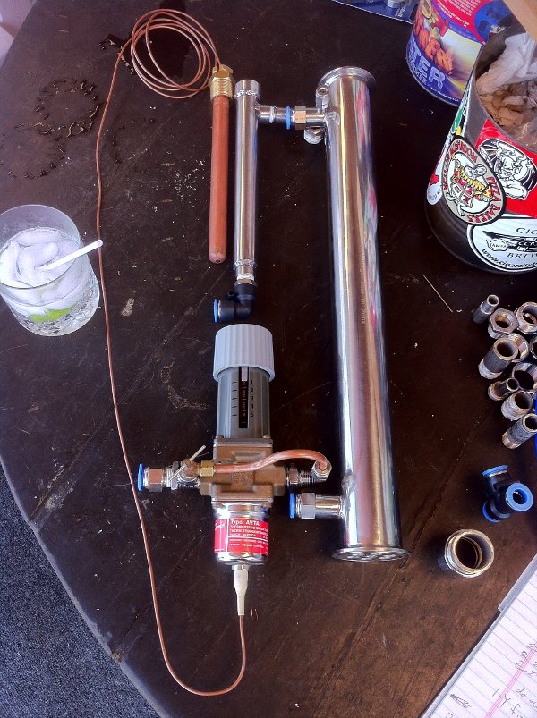
This next picture shows the valve body connecting to the inlet of the SD product condenser via a 1/2" x 3/8" SS hex nipple reducer, and the copper bypass pipe going into the compression fitting welded to the SD condenser.
Incredible, looking forward to the continuation of this thread and how it all works in practice.
StillDragon Australia & New Zealand - Your StillDragon® Distributor for Australia & New Zealand
+1 Very cool stuff. Has Rusty seen your mods yet?
StillDragon North America - Your StillDragon® Distributor for North America
I'm enjoying this!!
Excellent description on your process so far CD.
Your welds look perfectly fine to me :D
+1
Your Place to be >>> www.StillDragon.org <<< Home of the StillDragon® Community Forum
Lots of leaks on first test, but expected that, I hate torquing the heck out of things unnecessarily. 2nd test had no leaks, and proved the concept, started with the needle valve just cracked for bypass water. Since I am using 60psi water, the valve would open and a huge amount of water would go rushing through, and then the valve would close... it settled down after a few of these pulses, but it needs the 'P' of what a PID controller would do to be lowered if operating at a high pressure..... If you had a large enough condenser to fit the bulb into the condenser body, that would be best... also, I have the return water mixed with the dephleg, so seeing the flow of each was not possible, will separate them just to see the different flows... I am able to control the exit water temp very well, have tried various temps between 30-50C, and it works great... It takes several turns of the knob to move the temp few degrees... I have it about in the middle, and since it is a 25-65C valve, the middle is 45C, so the thing works as advertised... Even when I shut off the dephleg, it just starts sending more cooling water through the condenser to keep the same temp...
I consider it a complete success.
The major issue now is that I need a more efficient condenser... I want to be able to set the thing at 60C+ and have just a trickle of water used, but also have the parrot not be warm... So... if you think this is nice, wait until you see the next project, now designing a coaxial post-chiller to run the cooling water through first before it goes to the condenser.....
Oh, the think adds a bit of weight that is off center, so I rotated it around 90 degrees, you will want to rotate it as much as you can back towards the center column, or provide some support if you want it hanging straight off the condenser.
CothermanDistilling, if needed you can also join another condenser inline with your existing 20" shot gun. Adding our smaller version would give you nearly 30" of condenser. Just thinking out loud.
StillDragon North America - Your StillDragon® Distributor for North America
yeah, that would give a linear increase... I just think that 'time in contact with the condenser' of the product needs to be increased, need a spiraled 6' long leibig or something to slow the trickle down... like this spiral, dual tube condenser Maybe a standard condenser with the convoluted tubing (Since @Lloyd 's factory does not have good luck with copper to stainless welding, maybe just the convoluted stainless??...) I can't help but think that this would cool the trickling product 2-3x better than straight down the side of a tube.. maybe a piece of copper wire wound around a small rod and then pulled into the condenser tubes?
So you are thinking "Graham" condenser? In our library we do have a system that includes a Graham. Just not sure how well a single component prices out. That's really Lloyd's department.
StillDragon North America - Your StillDragon® Distributor for North America
no... true counter flow... basically a helically twisted liebig, so that you can have a 10' long liebig in 8" space...
picture this, with the inlet and outlet pointing up and down, but the coil staying like it is... it clamps on below the surge breaker, and either the parrot hangs lower, or you make a parrot that has a shorter inlet but is longer sideways... (basically this takes up the vertical space of the parrot inlet...
Coaxial Heat Exchanger (SR Series) - 5
Ah, Myles fabbed up one of those as i recall
StillDragon North America - Your StillDragon® Distributor for North America
Would all the ridges in the inner pipe cause smearing?
simple answer.. yes
long answer... less volume than the parrot body, and you could have this bypassed/removed during fores/heads/tails, it is really just to get the distillate to the cooling water temp for correct parrot reading and to have the lowest water consumption possible during the hearts run..
of course now you have me thinking that a water-jacketed parrot body would be a 'cool' solution... pun intended...
So the smallest Kv value for these guys is 1.4 cubes an hour.
I'm actually surprised your getting them to work all.
Yours should have an orifice size of 15mm and a Kv value of 1.9 m3/h!!
That's a whole lot of flow at 60psi, like nearly 15gal/min when fully open.
What sort of flow rate do you typically have through a run and is that with the bypass still cracked?
I disagree... the math says that with a 40 degree C rise in cooling water through a product condenser, 60% ABV requires 3.2liters/min for 20L/hr of distillate (95%ABV drops it to 2.3)
vapor to liquid: flowrate * evaporation enthalpy .0667kg/min * 1407.4kJ/jg 469.13 kJ/min
liquid cooling: flowrate * heat_capacity*(Tout - Tin) .0667kg/min * 4.184kJ/jg * 60 72.968 kJ/min
Total energy needed 542.1013333 kJ/min
Water needed:
Energy / heat_capacity*(Tout - Tin)
542kJ/min / 4.184kJ/jg * (60-20)
3.239133206 l/min
194.3479924 l/hr
Oh, here is the thread that links the .xlsx that does the math
With what?
15gal/min is a hell of a lot more than 3.2 l/min (like 15x more), which was my point.
I was just surprised that the valve was comfortable operating that low.
There is a much simpler way to do that math BTW, instead of going backwards from the output just look at the boiler power :)>-
I disagree with "I'm actually surprised your getting them to work all."
The things work awesome.. and I mean really frickin' awesome... best automation move I have done to date...
They come in three or four sizes of valve, they are standard, included equipment on a Kothe, Carl, Holstein, and even the DYE Chinese stills...
The Cv of mine is 2.2Gpm @ 1psi, per Danfoss. I am using about 10psi band 2.2gpm ( I do not often have a 40C delta) (but have used 60psi and it was a bit bouncy when used with less than 5500W, but the bypass could calm it down to be stable)
FYI - I only have the bypass cracked because the capillary tube is not inside the still, and the capillary would never get warm if there were no flow...
OK, so you don't run it at 60PSI. That make a bit more sense.
@ 60PSI I'd put money on the the bypass line doing almost all the work.
Those big guys that using them standard would be using a butt load more water and, at a guess, a lot less pressure too.
I did run it at 60psi on a 4" standard Dash-1 in the beginning of this thread...
Quote from Sep 3 2013:
yeah, I did read it. That 'P' is an oversized valve for the pressure that was being used.
yep... but I grew into it ;-)