
Welcome!
Be part of our community & join our international next generation forum now!
Categories
In this Discussion
- bbok March 2016
- CothermanDistilling May 2016
- gixxerpilot750 March 2016
- grim May 2016
- jacksonbrown May 2016
- Johnboy March 2016
- Mickiboi May 2016
- punkin March 2016
- Sandman March 2016
- TheMechWarrior March 2016
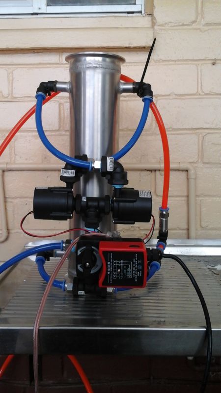
Full Flow Condensing System with Mixing Valve
My new condenser setup. It recirculates about 20 litres a minute through the condenser. Cooling water is mixed in with the recirculation water at suction point of the pumps using the 3 way valve. It is feed from the top down using 2 X 24vdc micro pumps. Hot condenser water is displaced from the system via the bottom suction. The condenser is now the same temperature all over. I have an electrician mate coming over with a thermal imaging camera to take some pictures of this running a neutral distillation and also will remove this setup and do it again the old way most other people are doing it using the needle valves and minimum flow setup and take more pictures. There is going to be a marked difference in heat distribution in the condenser. There is no mucking around with CV calculations and all that other bullshit. It looks complicated but it's not. Cost was 25 x 2 for the 2 pumps and 45 plus delivery for the mixing valve and 40 for pid controller. A small aquarium pump is all thats needed for the feed. Very little pressure is needed to run this. It will happily run fro mains pressure as well.
I am controlling using vapour temp and not condenser water temp.
Once its purged or air it wont drain down as long as the valve is in full flow position.
I have used this setup before on pharmaceutical jobs.
The response time in responding to condenser water needs for our purposes is virtually instant.


Comments
Looks good, keen to see where it goes.
You might want to consider a flow switch for safety's sake considering the price of those pumps.
The pumps are TopsFlo solar hot water pumps. My mum's solar hot water has 2 and they haven't failed after 5 or 6 years but she has gone through a couple of davey circulation pumps in the same time.
But thinking about it, I will move to a programmable controller as there is other things I want to control and monitor, including now the current of the 24vdc power to the pumps.
It works excellent.
Love it. Looking forward to seeing how this progresses
So the controlling probe is the one above the delph?
Thats the really interesting bit.
Can you go into a bit more detail in that? I don't think I've ever seen one that actually worked although many have tried.
What's the set point? Normally an overshoot would shut the thing down and cause a massive swing the other way
The overshoot you speak of, I believe, is with the needle valves you are feeding in cooling water at a very slow rate, usually at the bottom of the condenser. The condensing tubes would have different temperatures all over them, cooler at the bottom, hotter up the top, not what you want. Injecting more cooling water makes the problem worse. The bottom gets colder and the top stays the same temperature.
Pushing the water through at 20lpm and mixing in a tiny amount of cooling water means you have effectively changed the entire condenser surface temperature almost immediately, not just tiny parts at the bottom of it while leaving the top hot and above the condensing temperature of ethanol.
This way the entire tube condensing surfaces are all at the same temperature. This is the ideal situation for a condenser, same temperature all over.
Nothing more to progress, it works and it works bloody great. All am I going to do is change out the stand alone PID controller and use a programmable one to control my elements.
Its very cheap to put together.
I think this is the most effective way to maximize dephlegmator or product condenser surface area.
You can significantly increase the internal turbulence as well as reduce the delta-T to nearly the theoretical maximum with it.
You could probably drop that dephleg on a column double the size, or use a dephleg half the size.
We still have our PC hooked up like this, and we can push through an ungodly throughput. We switched the RC, because we can't mount a pump on the RC (XP/Classification). Take this one step forward, I actually considered using both ports on one side as a fixed recirculation loop on the condenser, and using the opposite side as the input/output.
Moving the valve/pump on the dephleg will make managing overshoot much, much easier, as the dead time is nearly zero.
I think I need to see it as a P&ID, I just can't see it...and I so want to see it! :)
By the way, with this approach you can probably use paired solenoids instead of the valve and get lightning fast response times.
You can hear and feel the turbulence. I had it running, no Derivative. Slight over shoot by about 0.15DegC but it settled out in about 10 seconds. I'm not a big fan of using Derivative. Usually its more trouble than its worth and I have always tried to make my loops work with out it.
What can't you see Mech? What isn't making sense to you.?
So your loop is being feed by mains pressure and the max flow of fresh coolant into the 3 way is tuned with an upstream needle valve?
The overshoot I was talking about was at 100% RR your temp plumets as there's no vapour on probe. With a set point of 78.3 you can't get a temp much under that. I would have though a pid wouldn't behave well under those conditions. Some more run info would be great. Inlet outlet temps too.
Maybe the high flow rate, lightning response time is the key.
Me too.
So what is the set point? What are you making with it.
The cam should show any air traps in the system which will be interesting.
What was you reasoning behind the flow down approach?
No needle valves. The mixing valve has a much smaller inlet port compared to the flow through ports. First pic is flow through, second pic is mixing port.
There is vapour on the sensor, even at 100% RR something is escaping the condenser. Put your rig into 100% without a top on the condenser and smell whats coming out of it. There will always be gases escaping. Always.......unless you have the condenser below zero.
The water is pushing through at such a huge rate, air in the top 10mm of the condenser is not a problem. It is fed top down for 2 reasons. 1 is counter flow, coolant from the top, vapour from the bottom, which everyone always talks about but with these huge flows probably not really important here. Second is the pumps suck from the bottom, there is always water at the bottom so even if the condenser is not totally full its not going to run dry. I might make myself a little air bleed valve and modify the condenser but at this stage, not going to bother.
The setpoint is what ever you want it to be. If you set it to 70 degc then the vapour passing the condenser will be......70degc. If you set it 40degc then the vapour passing the condenser will be 40degc.
I wish you were standing beside me to see it operate, it would all make sense when you see it running, changing setpoints, etc.
As for the Derivative, Iike I said in previous posts all over here, I don't use it. To properly tune a loop using Derivative even tests me. So why use it when its really not needed in such a simple process as controlling a vapour temp?
The other thing is lag. Temperature sensor lag and valve opening lag. I can almost bet you that when you apply 4.1mA or 0.15 volts or whatever your valve requires, the motor will have driven but it wont have opened to allow water through, they never do. You need a controller that has a scalable output high/output low. eg. 100%open = 20mA and 0% open = 4.12mA or whatever the point is your valve cracks. Thats the first point of lag in the system. Second is the temperature sensor. I sourced Pt100 elements. They are encased in ceramic. It is virtually everything proof. The tip is directly exposed to the vapour. Very small amount of lag there.
Loops expect to see a change when they change the output. There is no point trying to tune a loop if nothing happens when the loop changes.
Me too because there's quite a few points you're making that don't make a lot of sense to me but I'm glad it's working well for you.
Looking forward to the run info.
Ask away.
If you understand air conditioning then it's really no different than maintaining a constant leaving air temperature. It's a very simple process.
It's not really though, is it?
Air doesn't condense and vapour isn't cooled.
I thought I had a reasonably firm grasp of the fundamentals but very keen to fill any gaps.
Ok. It is the same. I know we are not condensing air, but if the condenser was cold enough it would condense the air into its separate components . I could monitor the leaving temperature and separate the nitrogen, oxygen and all the gases one by one.
The components of a wash is no different, lots of components all condensing at different temperatures. I dont care what the condenser is doing temp wise. Im only interested in the temperature of what's coming out the top.
PM sent
Got it. I will post a video shortly when the programmable controller arrives.
I vote this idea of the year. This makes a bunch of sense. Can’t wait to try it.
With the respect to the “old way” I would propose that even with a perfect valve and no dead time on your rtd the old way can’t be tuned very well due to the dead time within the condenser. I tried briefly but couldn’t see it ever working so I always controlled the water temp, which is mediocre as you have to keep adjusting to achieve constant vapor temp throughout the run.
So now on a neutral run at Azeo, I shouldn't have to worry about heads and tails cuts just set my heads cut temp .2 of a degree below ethanol boiling temp when it stops dripping heads are done. Readjust to .2 below tails temp collect hearts. When it stops dripping hearts is done shut her down.
Am I understanding that correctly?
You know what heads temp, hearts temp and tails temp are for a particular run?
StillDragon Australia & New Zealand - Your StillDragon® Distributor for Australia & New Zealand
Sure for neutral. If you're pulling az, then anything above and below 78.2
You won't be doing that on a plated column though.
I should add, if you're going to run on a knife edge like that you'll be needing pressure compensation like the electric parrot.
A rainy day or a bit of elevation change will throw all your temps out.
So 78.2 for every wash? (of course 90% of the people here are not 'pulling az').
StillDragon Australia & New Zealand - Your StillDragon® Distributor for Australia & New Zealand
Pulling something else?
I never got it to work, while this design is superior, but needs everything sized and tuned nearly perfectly to not drive you nuts. Cobbling together random parts won't work.
I tried this really early on, this was the first model I tried, and I'm guessing the dead time was what killed me. The relationship is not:
dephlegmator temperature -> vapor temperature
it is:
dephlegmator temperature -> change in reflux ratio -> column re-equilibration -> new vapor temperature
That's much more complicated than a single order relationship where the control variable directly impacts the process.
Honestly, I think it would be easier to manage this kind of setup with an LM rig, where you are using the vapor temp as input to the PID, controlling the LM reflux rate directly.
Mickiboi,
Would you mind posting a few more pictures of your setup in addition to the specific model pumps and mixing valve used? I was wondering about a detail not included in the first picture...on the bottom right outlet from the condenser does the heated water come out into a tee where it can either be discharged from the system or fed back into the mixing valve? I assumed this because the red hose was ziptied up so as to not allow air into the system.
This setup seems remarkably similar to a radiant in-floor heat system where water would be used as the heat exchange medium and available for domestic hot water. I could be completely wrong about this as I don't know a whole lot about plumbing, but it seems similar in my mind. If it is similar, would some form of backflow prevention or a check valve help in any way to prevent the system from draining down or sucking air into the system?
@grim
I did do a lot of sizing and flow checking while doing spirit runs connected the coventional way using this valve as a two way and a 4-20mA current generator and a calibrated temperature meter. I had a flow meter and pressure sensor on the injection inlet. There is about 32kpa pressure drop across my condenser using the 2 pumps. I spoke to Raf at belimo in Melbourne and sent him my design, he said go with what i have got. Mixing condenser water and cooling water is much easier to do and get it right than using a conventional CV approach using a 2 way valve. In a 2 way valve setup maintaining correct pressure on the inlet of the valve and knowing the pressure drop of the coil/condenser is critical in sizing. If anyone wants a lesson in valves call Raf. He loves talking valves.
After I plumbed it all up as it is in the pics, in the end it really didn't make much difference whether I used mains or a cheap arse aquarium pump. The valve just doesn't open as much under mains. I also dropped the injection water hose in the coolant tank and it sucked it in anyway.
It worked but worked a bit slower with one pump so I put on another pump. I did size it for 10 litres a minute, it worked but the still a bit slow in the responce.
This is basically the temperation loop that I keep pushing.
That valve should still have a cv value, you just got it right without looking.
Is it a two way with a built in tee or a full divert valve.
The pressure drop with the high flow rate is interesting. Did you take off 5 kPa for the static head (height difference). Leaving the pressure gauge on the bottom port and turning the flow on and off would give the exact figure.