
Welcome!
Be part of our community & join our international next generation forum now!
Categories
In this Discussion
- CothermanDistilling September 2015
- grim September 2015
- vooharmy September 2015
Help me decipher this Wiring Thingy!
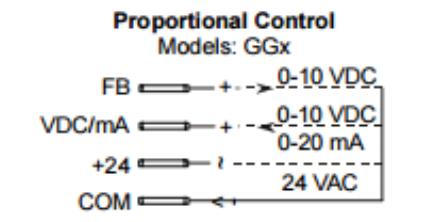
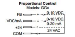
Hey guys I am looking at this wiring diagram for a Johnson actuator, and its not making a great deal of sense to me. Its the common that's confusing me, So does the -negative for the control signal and the -negative for the 24VAC power share the same -negative? Or is the Feedback the Negative for the control signal? Not too knowledgeable on these things and don't want to fry the actuator, I know a few people have used these previously just looking for some insight. The setup I am using has the following pieces , the Power supply is a 24vac 3.2va transformer, PID is a C700 powered by 240v. I am guessing that the following is correct but I am just as likely to be wrong!
FB = mA -negative
VDC/mA = mA +positive

+24 = 24VAC +Positive
COM = 24VAC -Negative
Comments
common is connected to both one leg of the 24vac and to the negatavie of the voltage/current.
If your particular C700 is not a 'current output' model, DO NOT HOOK IT UP.... You need a PID that outputs 4-20mA (you may have this, but you did not say, and they are not the most common, the label on the side of the PID needs to say "OUTPUT - CURRENT"
if you search ebay for the following three words, it will show someexamples of what you need: pid current output
If it is the current output model, nevermind the above...
Here is link to the thread I did a writeup on, with a pic of the wiring of the Johnson to a Sestos.
Ignore the FB (Feedback) wire, it's not necessary, it is not the negative at all, it's a feedback signal to a special kind of controller.
Common is the ground for both the 24vac AND the VDC/mA proportional control like @CothermanDistilling says.
this one pic, on the thread I linked, has almost everything you need to get it working:
I have the 4-20ma PID, it appears from what your saying that the 24vac transformer provides the power for the current signal? My confusion is that I thought the current output was a signal and the 24ac was to power the actuator ie totally separate!
More like this?
they just share the ground...
it may be confusing, but AC and DC can have the same ground...
the picture you have has the labeling very confusing, I edited it.. might make it more confusing